
We have some technical issues with the website.
NEW: See announcements.
NEW: See announcements.
Radio Control for Model Trains
Support and information
This page is organised into four sections
- General information and support
- Information and support for RCT Transmitters
- Information and support for RCT Receivers
- Downloads
General information and support
How do I get started with battery power and radio control?
On my blog, I have created various guides over the years. If you are starting out with radio control, you might find them useful:
Is the RCT/Deltang system compatible with other radio control systems?
Yes! RCT/Deltang uses the well established and highly respected DSM2 system. RCT transmitters can control conventional DSM2 receivers and RCT receivers respond to conventional DSM2 and some DSMX transmitters.
Does the Selecta system work with other radio control systems?
Yes, to some extent! It is possible to 'select' Selecta-enabled receivers by using the trim control for Channel 2 on a conventional transmitter. As each position on the Selecta switch covers about seven trim-clicks, the trim control on a conventional transmitter should be able to access around five different receivers bound to RCT/Deltang transmitters.
Why should I use RCT/Deltang equipment?
All I can do is give you my reasons for opting for Deltang equipment. I started using Deltang equipment in 2012 when it was a fairly new system available for garden railway enthusiasts. What I liked about it was:
How do I get started with battery power and radio control?
On my blog, I have created various guides over the years. If you are starting out with radio control, you might find them useful:
- Getting started with battery power and radio control
- An evaluation of Deltang radio control (written in 2013, but still valid)
- Getting started with Deltang Radio Control
Is the RCT/Deltang system compatible with other radio control systems?
Yes! RCT/Deltang uses the well established and highly respected DSM2 system. RCT transmitters can control conventional DSM2 receivers and RCT receivers respond to conventional DSM2 and some DSMX transmitters.
Does the Selecta system work with other radio control systems?
Yes, to some extent! It is possible to 'select' Selecta-enabled receivers by using the trim control for Channel 2 on a conventional transmitter. As each position on the Selecta switch covers about seven trim-clicks, the trim control on a conventional transmitter should be able to access around five different receivers bound to RCT/Deltang transmitters.
Why should I use RCT/Deltang equipment?
All I can do is give you my reasons for opting for Deltang equipment. I started using Deltang equipment in 2012 when it was a fairly new system available for garden railway enthusiasts. What I liked about it was:
- Its simplicity - it's very quick to get started and up and running.
- The receiver is very small and yet includes an electronic speed controller (ESC)
- Binding the transmitter and receiver is a very straightforward process.
- A knob controls the loco's speed and direction rather than a joystick
- One transmitter (which is handheld) can independently control up to 12 locos
- It's very cost effective - a combined receiver and ESC costs less than most ESCs
- The receivers have several output (or input) pads which can be re-programmed
- It's reliable. Very rarely have I had any problems and those that I have had were mostly caused by user error
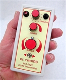
Information and Support for RCT Transmitters
How long do the batteries last in the transmitter?
This, of course, depends on how often the transmitter is used. I reckon on replacing the PP3 battery in each of my transmitters about once a year.
What sort of range does the transmitter have?
The transmitters have a range of about 30 metres, but that can vary if there are buildings, dense foliage or people in the way. My garden is around 25 metres from one end to the other and I have no problem transmitting over that distance. One of my locos sometimes loses its signal when it goes behind the sheds, but that loco has a metal body which shields the receiver aerial (antenna) and so the range is reduced.
What is the best way to hold the transmitter?
For the most reliable results, the aerials inside the transmitter and the receiver in a loco should be parallel with each other. The aerials inside all RC Trains transmitters are positioned towards the top of the transmitter case, generally pointing upwards. This helps ensure the aerial is not shielded by your hand when you are holding the transmitter. Rather than pointing the transmitter at the loco (as you might do with a TV remote control), you should hold the transmitter vertically to optimise the transmission of the signal.
Why does the transmitter have a direction switch?
Because, receivers can be re-programmed to operate using it - the speed knob then controls the loco's speed over its entire sweep. Direction can only be changed when the loco is stationary (you'll be pleased to hear - much less harmful to the loco's mechanism). When the receiver is programmed for centre-off (ie the speed knob controls both speed and direction), the direction switch can be used to control accessories. My railcar's interior lighting used to be controlled by the direction switch but I now use it to control the railbus's MP3 player 'soundcard' (see My blog posting).
How is the receiver bound to the transmitter?
The receiver is put into bind mode (see below). The bind button is held down while the transmitter is switched on. After about five seconds the transmitter and receiver are bound together. They remember their bind settings when switched off and subsequently switched on again.
What happens when the Selecta switch on the RCT-Tx22 is moved to another position?
Just like when the transmitter is switched off, any locos which are running will continue to run at the same speed and in the same direction until the Selecta switch is turned back to the position which controls that particular loco.
How many receivers can be bound to each transmitter?
As many as you like. There are twelve positions on the Selecta switch, but several receivers can be bound to each position on the RCT-Tx22 and RCT-Tx24. Provided only one receiver per Selecta switch position is switched on at any one one, then only that loco will respond when the switch is turned to that position.
Information and support for RCT Receivers
What's the difference between the Rx65c and the Rx102?
Basically (apart from the price), the Deltang / RCT-Rx65c includes an electronic speed controller (ESC) on the same board as the receiver while the Deltang / RCT-Rx102 is a DSM2 compatible receiver only. The Deltang / RCT-Rx102 can be used to control ESCs, soundcards and servos, just like any other DSM2 receiver.
What happens to the Rx65c if my motor needs more the 3 amps?
This is one good reason why it is advisable to include a fuse in the circuit in your loco as it is possible to 'blow' the receiver. If you know your loco's motor will probably draw more than 3 amps, then it is advisable either to buy the additional 'daughter board' from Deltang or to buy the RCT-Rx102 and use a separate ESC which is designed to handle more than 3 amps. I have twelve battery powered locos - all of which draw far less than 3 amps.
Can I use the Rx65c if I want to power my locos with more than 18 volts?
Although the receiver is constructed with components rated at 20v, it is safer to have a margin and so the maximum recommended voltage is 13v. As above, the more immediate solution is to use an Rx102 with a third party ESC which is rated for higher voltages such as the Brian Jones Mac 5 SA which can handle up to 24 volts.
Can the RCT-Rx65c be used with track power?
In theory, yes, but in practice a couple of customers who tried it abandoned their attempts because the supply from the rails was too erratic. By contrast, onboard batteries provide a smooth and constant supply of power and hence are ideally suited to the electronics circuitry on the receiver boards.
Where's the best place to install the receiver in my locos?
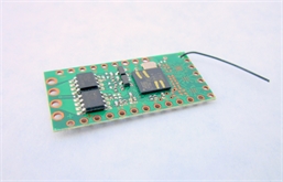
As indicated in the section on transmitters, the ideal is for the aerials in the loco and the transmitter to be parallel with each other. When positioning the receiver in your loco, try to ensure it is vertical. If it is lying horizontally, then there may be occasions as the loco negotiates your railway when the aerial is pointing at the transmitter rather than being side-on to it. 2.4gHz signals can be shielded by buildings, people, undergrowth and metal loco bodies and so the best position for the aerial is as high up on a loco as possible, preferably not encased within the metal body. The receiver will still work successfully if this sort of positioning is not possible, but its range will be diminished (see also - examples of receiver installations in live steam locos)
Can I make the aerial on the receiver longer?
Not easily. The length of the aerial on the receivers is a precise 31mm - this equates to 1/4 of the wavelength of the 2.4gHz signal used by the transmitter. If you lengthen the aerial, you will actually reduce its acuity. It is possible to solder a coaxial IPX connector to the receiver (and transmitter) circuit board but it is a very fiddly process. This allows for the connection of a shielded cable leading to an aerial which can be positioned unobtrusively outside the metal body of the loco. Receivers with extended IPX aerials can be supplied by RC Trains and Deltang at extra cost.
How are LEDs connected to the Rx65 for directional lighting?
The Rx65c has two sorts of outputs for directional lighting. Pad 1 (forward) and Pad 2 (reverse) provide 3.5v output and can be connected to the anode (ie the positive lead) of each LED through a current limiting resistor (value 150ohms or more) and the other leg of the LED (ie the cathode) is connected to the negative terminal of the battery. Pad A (forwards) and Pad B (reverse) provide 0v output depending on the direction. The pads are therefore connected to the cathode (negative) lead of each LED and then a current limiting resistor is connected to the anode (positive) lead and then on to the positive terminal of the battery supply. The value of the resistor will depend on the supply voltage. A useful calculator for the resistor value can be found here - http://www.hobby-hour.com/electronics/ledcalc.php
How are LEDs connected to the Rx102 (eg for the directional lighting)?
The uppermost Pin 6 (forward) and Pin 7 (reverse) provide 3.1v for directional lighting LEDs. The receiver includes a current limiting resistor and so leads from the pins can be connected directly to the anode (positive) leads of the LEDs and the (cathode) negative leads connected to the negative terminal of the battery.
Can the receivers be used to control miniature light bulbs?
Yes, light bulbs can be used but only with output pads A, B or C on the Rx65b. However, as the maximum current draw from the receiver is 3 amps, you need to ensure that the overall current drain on the receiver is not excessive. LEDs draw considerably less current and so are a much safer option for lighting. If you did want to use miniature light bulbs I would recommend constructing some sort of relay or a transistor switch (eg see A simple transitor switch circuit).
How do I control soundcard effects with the Rx65c?
The Rx65c has several output pads which can be used to control soundcard effects. Most soundcards require 0v to trigger effects such as the horn or whistle. Pad C provides 0v in response to the bind button being pressed on the transmitter. If a lead is connected from Pad C to the sound trigger terminal, then that sound will occur when the bind button is pressed. I usually connect the horn or whistle trigger to Pad C. Further effects can be triggered by the direction switch on the transmitter. Pads 9 and 10 provide 0v in response to the direction switch being flicked one way or the other. A lead from Pad 9 connected to a trigger on the soundcard will make that sound happen when the direction switch is flicked to the left. It is important that the receiver and the soundcard use the same battery supply or, if separate batteries are used to power the receiver and the card, then the negative terminals of each battery supply are connected. Also, the components on soundcards are usually powered by a regulated 5v supply, whereas the receiver uses 3.1v. It's advisable, therefore, to protect the receiver from excess current by including a 1k resistor in the lead from the pad to the soundcard trigger.
Can soundcard effects be controlled with the Rx102?
As supplied, the Rx102 does not have outputs which can be used to trigger soundcard effects (ie it does not have any 0v outputs). However, it can be reprogrammed to provide 0v outputs.
How are receivers reprogrammed?
See my blog entry on programming Deltang receivers - http://riksrailway.blogspot.com/2015/11/programing-deltang-receivers.html
What's the difference between the Rx65c and the Rx102?
Basically (apart from the price), the Deltang / RCT-Rx65c includes an electronic speed controller (ESC) on the same board as the receiver while the Deltang / RCT-Rx102 is a DSM2 compatible receiver only. The Deltang / RCT-Rx102 can be used to control ESCs, soundcards and servos, just like any other DSM2 receiver.
What happens to the Rx65c if my motor needs more the 3 amps?
This is one good reason why it is advisable to include a fuse in the circuit in your loco as it is possible to 'blow' the receiver. If you know your loco's motor will probably draw more than 3 amps, then it is advisable either to buy the additional 'daughter board' from Deltang or to buy the RCT-Rx102 and use a separate ESC which is designed to handle more than 3 amps. I have twelve battery powered locos - all of which draw far less than 3 amps.
Can I use the Rx65c if I want to power my locos with more than 18 volts?
Although the receiver is constructed with components rated at 20v, it is safer to have a margin and so the maximum recommended voltage is 13v. As above, the more immediate solution is to use an Rx102 with a third party ESC which is rated for higher voltages such as the Brian Jones Mac 5 SA which can handle up to 24 volts.
Can the RCT-Rx65c be used with track power?
In theory, yes, but in practice a couple of customers who tried it abandoned their attempts because the supply from the rails was too erratic. By contrast, onboard batteries provide a smooth and constant supply of power and hence are ideally suited to the electronics circuitry on the receiver boards.
Where's the best place to install the receiver in my locos?
As indicated in the section on transmitters, the ideal is for the aerials in the loco and the transmitter to be parallel with each other. When positioning the receiver in your loco, try to ensure it is vertical. If it is lying horizontally, then there may be occasions as the loco negotiates your railway when the aerial is pointing at the transmitter rather than being side-on to it. 2.4gHz signals can be shielded by buildings, people, undergrowth and metal loco bodies and so the best position for the aerial is as high up on a loco as possible, preferably not encased within the metal body. The receiver will still work successfully if this sort of positioning is not possible, but its range will be diminished (see also - examples of receiver installations in live steam locos)
Can I make the aerial on the receiver longer?
Not easily. The length of the aerial on the receivers is a precise 31mm - this equates to 1/4 of the wavelength of the 2.4gHz signal used by the transmitter. If you lengthen the aerial, you will actually reduce its acuity. It is possible to solder a coaxial IPX connector to the receiver (and transmitter) circuit board but it is a very fiddly process. This allows for the connection of a shielded cable leading to an aerial which can be positioned unobtrusively outside the metal body of the loco. Receivers with extended IPX aerials can be supplied by RC Trains and Deltang at extra cost.
How are LEDs connected to the Rx65 for directional lighting?
The Rx65c has two sorts of outputs for directional lighting. Pad 1 (forward) and Pad 2 (reverse) provide 3.5v output and can be connected to the anode (ie the positive lead) of each LED through a current limiting resistor (value 150ohms or more) and the other leg of the LED (ie the cathode) is connected to the negative terminal of the battery. Pad A (forwards) and Pad B (reverse) provide 0v output depending on the direction. The pads are therefore connected to the cathode (negative) lead of each LED and then a current limiting resistor is connected to the anode (positive) lead and then on to the positive terminal of the battery supply. The value of the resistor will depend on the supply voltage. A useful calculator for the resistor value can be found here - http://www.hobby-hour.com/electronics/ledcalc.php
How are LEDs connected to the Rx102 (eg for the directional lighting)?
The uppermost Pin 6 (forward) and Pin 7 (reverse) provide 3.1v for directional lighting LEDs. The receiver includes a current limiting resistor and so leads from the pins can be connected directly to the anode (positive) leads of the LEDs and the (cathode) negative leads connected to the negative terminal of the battery.
Can the receivers be used to control miniature light bulbs?
Yes, light bulbs can be used but only with output pads A, B or C on the Rx65b. However, as the maximum current draw from the receiver is 3 amps, you need to ensure that the overall current drain on the receiver is not excessive. LEDs draw considerably less current and so are a much safer option for lighting. If you did want to use miniature light bulbs I would recommend constructing some sort of relay or a transistor switch (eg see A simple transitor switch circuit).
How do I control soundcard effects with the Rx65c?
The Rx65c has several output pads which can be used to control soundcard effects. Most soundcards require 0v to trigger effects such as the horn or whistle. Pad C provides 0v in response to the bind button being pressed on the transmitter. If a lead is connected from Pad C to the sound trigger terminal, then that sound will occur when the bind button is pressed. I usually connect the horn or whistle trigger to Pad C. Further effects can be triggered by the direction switch on the transmitter. Pads 9 and 10 provide 0v in response to the direction switch being flicked one way or the other. A lead from Pad 9 connected to a trigger on the soundcard will make that sound happen when the direction switch is flicked to the left. It is important that the receiver and the soundcard use the same battery supply or, if separate batteries are used to power the receiver and the card, then the negative terminals of each battery supply are connected. Also, the components on soundcards are usually powered by a regulated 5v supply, whereas the receiver uses 3.1v. It's advisable, therefore, to protect the receiver from excess current by including a 1k resistor in the lead from the pad to the soundcard trigger.
Can soundcard effects be controlled with the Rx102?
As supplied, the Rx102 does not have outputs which can be used to trigger soundcard effects (ie it does not have any 0v outputs). However, it can be reprogrammed to provide 0v outputs.
How are receivers reprogrammed?
See my blog entry on programming Deltang receivers - http://riksrailway.blogspot.com/2015/11/programing-deltang-receivers.html
If you have questions which are not covered by these FAQs, then please ask me via the contact page.
Downloads (.pdf documents)

