LEDs
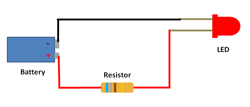
Light Emitting Diodes (LEDs) provide illumination but draw a lot less current than incandescent bulbs. They can therefore be powered by RCT/Deltang receivers without overloading them. LEDs themselves need protection from overload. This is usually provided by placing a resistor in series with the LED. The value of the resistor is dependent on the voltage being supplied to the LED (and the characteristics of the LED - see below).
Using LEDs with the RCT-Rx102 receiver
If you are using LEDs powered by the RCT-Rx102, then there is no need for an additional resistor as one (180ohm) is included onboard the receiver.
Using LEDs with the RCT-Rx65b receiver / controller
If you are intending to use an LED with the RCT-Rx65b, then the value of the resistor will be dependent on which output pads are being used.
- Pads 1-12 provide 3.5 volts positive output when triggered. The positive lead (anode) of the LED is therefore connected to the pad through a resistor with a value of at least 150ohms. The positive lead of an LED (anode) is usually longer than the negaitve lead (cathode). The negative lead of the LED is connected to the negative terminal of the battery being used to power the receiver. A pre-wired lead with a suitable resistor is available from RC Trains. It has an orange lead to help distinguish it from the other pre-wired LEDs.
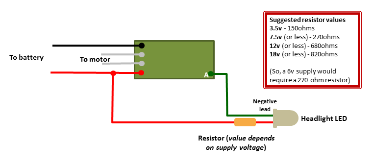
- Pads A, B and C provide 0v output when triggered. A lead from the one of these pads needs to be connected to the negative lead (cathode) of the LED. The postive lead (anode) of the LED must therefore be connected via a resistor to the postive terminal of the battery supplying power to the receiver. The value of the resistor will be dependent on the supply voltage being used.
- For 3.5v (or less), a 150ohm resistor is needed. Pre-wired LEDs for this voltage are supplied by RC Trains with an orange lead.
- For 7.5v (or less), a 270ohm resistor is rquired. Pre-wired LEDs for this voltage are supplied by RC Trains with a yellow lead.
- For 12v (or less), a 680ohm resistor is required. Pre-wired LEDs for this voltage are supplied by RC Trains with a red lead.
- For 18v (or less), an 820ohm resistor is required. Pre-wired LEDs for this voltage are supplied by RC Trains with a brown lead.
If, for example, your loco is powered by a 6v supply and you are using Pad A for its headlight, then you should use the 7.5v pre-wired LED. It will be slightly dimmer than when powered by 7.5v but not noticeably so.
Or, if your loco has headlights at front and rear ........
Please note: The exact value of the resistor required is also dependent on the characteristics of the LED being used. The above values are matched to the specific LEDs which are supplied by RC Trains. If you use LEDs from another source you should check their specifications to discover their forward voltage and maximum current and then calculate the precise value of resistor required. If in doubt, opt for a larger value resistor than those shown above. The precise value of the resistor can be calculated using online tools such as - http://ledcalc.com/
Head and tail lights
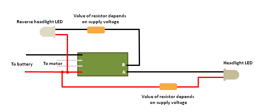
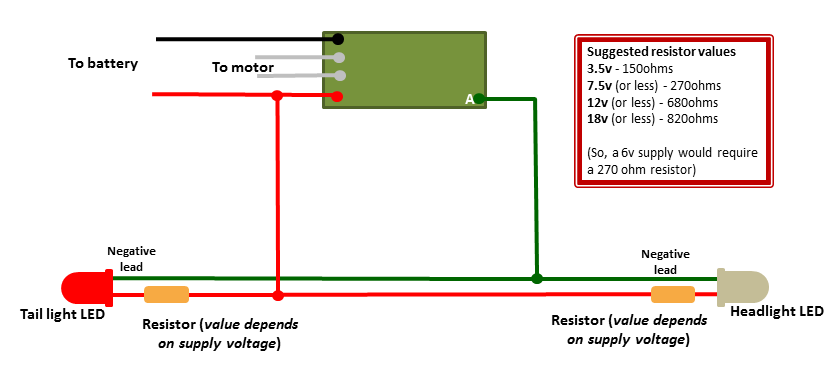
If you want the headlight and a tail light to come on automatically, then you need to wire both the head and tail light LEDs to the same pad, like this ......
If you want the headlight and a tail light to come on automatically, then you need to wire both the head and tail light LEDs to the same pad, like this ......
Or like this ..........
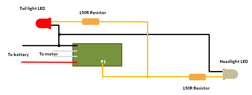
NOTE: If using pads 1 - 12 for lighting then you need to use a 150 ohm resistor as these pads give 3.2v when 'on' (or high)
Bi-colour LEDs
Bi-colour LEDs generally come in two types of packages - those with two legs and those with three legs.
Bi-colour LEDs with two legs are energised by reversing the input polarity - connect the two leads one way round on the battery supply and it will glow with one colour, connect it the other way round on the battery and it will glow the second colour.
The type of bi-colour LED which is most useful for use with RCT/Deltang receivers is the one with three legs. The two internal LEDs share the middle leg (cathode - negative) and the LED is made to glow one colour by connecting one leg to the positive supply and it will glow the alternative colour by disconnecting the first leg and then connecting the second leg to the supply. This makes it more suitable for switching with the output pads from the RCT/Deltang receivers.
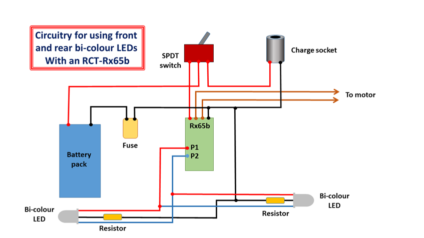
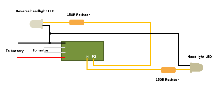
If using two LEDs (one for the front of the loco and the other for the rear), then the LEDs can be connected as below. When the loco runs forward, the front LED will glow white and the rear LED will glow red. When it runs in reverse, the colours will be reversed (ie red at the front and white at the rear).
Bi-colour LEDs generally come in two types of packages - those with two legs and those with three legs.
Bi-colour LEDs with two legs are energised by reversing the input polarity - connect the two leads one way round on the battery supply and it will glow with one colour, connect it the other way round on the battery and it will glow the second colour.
The type of bi-colour LED which is most useful for use with RCT/Deltang receivers is the one with three legs. The two internal LEDs share the middle leg (cathode - negative) and the LED is made to glow one colour by connecting one leg to the positive supply and it will glow the alternative colour by disconnecting the first leg and then connecting the second leg to the supply. This makes it more suitable for switching with the output pads from the RCT/Deltang receivers.
If using two LEDs (one for the front of the loco and the other for the rear), then the LEDs can be connected as below. When the loco runs forward, the front LED will glow white and the rear LED will glow red. When it runs in reverse, the colours will be reversed (ie red at the front and white at the rear).