
Deltang / RCT-Rx65c
Receiver / Controller
Receiver / Controller
The RCT-Rx65c is the most sophisticated receiver/controller in the range available from RC Trains. In addition to having an electronic speed controller (ESC) built into the board (which measures only 18x35mm (0.7x1.4")), the RCT-Rx65c has eleven output/input pads which can be programmed to provide a wide range of functions from operating LEDs and servos to triggering soundcard events.
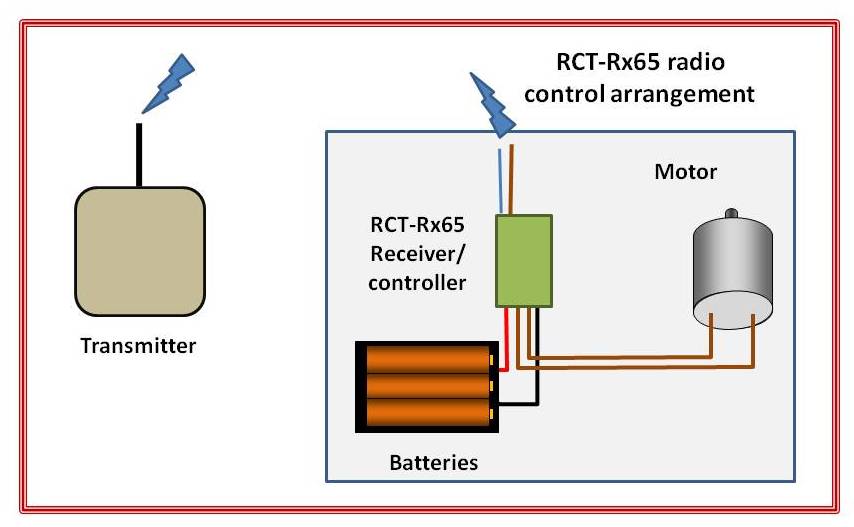
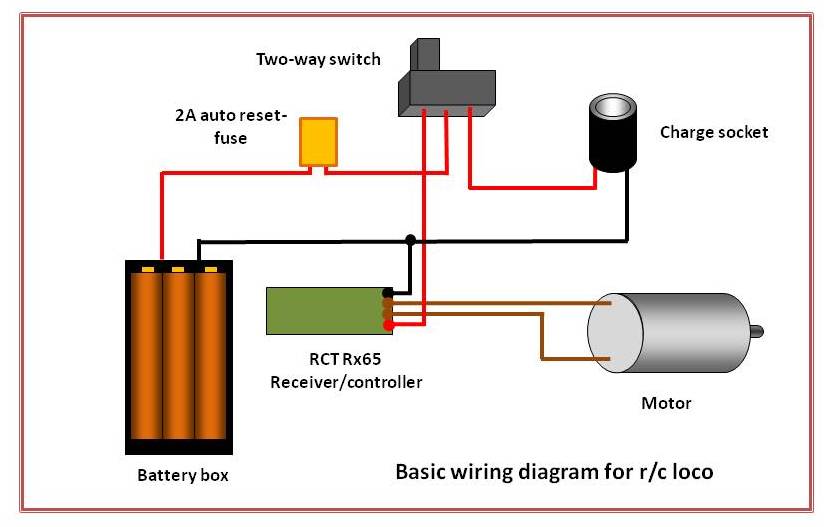
At its most basic level, wiring an RCT-Rx65c into a locomotive is extremely straightforward. Two wires are connected to the battery (or track) supply, two wires are connected to the loco's motor, the receiver is bound to the transmitter and away you go! I would, however, suggest that you include a fuse of some kind in the circuit to protect the batteries from short circuits and to protect the receiver / controller from becoming overloaded. The most practicable arrangement is to include a charging socket and a two-way switch (For more information see the Support section )
At its most basic level, wiring an RCT-Rx65c into a locomotive is extremely straightforward. Two wires are connected to the battery (or track) supply, two wires are connected to the loco's motor, the receiver is bound to the transmitter and away you go! I would, however, suggest that you include a fuse of some kind in the circuit to protect the batteries from short circuits and to protect the receiver / controller from becoming overloaded. The most practicable arrangement is to include a charging socket and a two-way switch (For more information see the Support section )
Versions
Four versions of the RCT-Rx65c receiver are currently available. Other versions of the receiver can be supplied on request.
Overview of the RCT-Rx65c's features
2.4gHz receiver compatible with DSM2/DSMX
The RCT-Rx65c uses 2.4gHz radio technology and is compatible with DSM2 systems. This means the radio signal is very stable and reliable, being less prone to interference than earlier systems. When a receiver is 'bound' to a transmitter, they create a unique coded signal to communicate with each other, meaning that several transmitters and receivers can safely operate together without the risk of conflicts.
Includes an integrated 3A reversible controller (ESC) for brushed motors
The RCT-Rx65c includes an electronic motor controller (ESC) which controls one loco motor without the need for additional components. This makes it very versatile and economical. It can handle loads of up to 3 amps.
Can be powered by 3-13v (1-3S lipo, 1-4 life, 3-8 nicads, 1 PP3)
Any type of battery can be used to power the RCT-Rx65 or it can be powered from the track. By default, the receiver is programmed to detect the number of lithium-ion batteries connected to it and will automatically cut-out if their voltage drops below safe levels (Low Voltage Cut-off (LVC)). This feature can be easily disabled the the user (or by me on request), if the receiver is going to be run with other types of battery (see paperclip settings)
Cruise Control / Failsafe
The RCT-Rx65c is set to Cruise Control by default. This means that if a loco loses the signal from the transmitter (eg when running through a tunnel), then the loco will continue running at the same speed and in the same direction until it regains the signal. This feature also allows the user to switch off the receiver (eg when a loco is running around a circuit or is in auto-shuttle mode) to save the transmitter's battery power. However this is not essential as I have found that, in general, the PP3 battery which is used to power the receiver lasts for around a year (though this will vary depending on how often the transmitter is used). This feature can be reset by using paperclip settings
Output pads
A great virtue of the RCT-Rx65c, is the number of output pads which it offers (11 in total) which can be used for a range of purposes. These pads are programmed by default to provide useful outputs but they can also be reprogrammed for other purposes.
Default settings for the pads on the RCT-Rx65c
Four versions of the RCT-Rx65c receiver are currently available. Other versions of the receiver can be supplied on request.
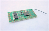
RCT-Rx65c Plain unwired version
The receiver board is supplied with no wires attached and no insulated heatshrink cover.
The user must solder his or her own wires to the pads on the board.
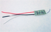
RCT-Rx65c Basic wired
Wires are soldered to the board for the battery input (3-13v) and for the motor output.
The board is covered in a clear plastic sleeve for electrical insulation.
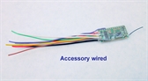
RCT-Rx65c Accessory wired
In addition to the battery and motor leads, five additional leads are soldered to output
pads. These are
- Pad 6 (Grey) - On/Off (Channel 3), Momentary action, 0v when channel is High - can be used to trigger soundcard effects using the direction switch (Direction 1)
- Pad 7 (Purple) - On/Off (Channel 3), Momentary action, 0v when channel is Low - can be used to trigger soundcard effects using the direction switch (Direction 2)
- F1 output 'A' (Green) - Front Light (auto), 0v when on disconnected when off - used to operate front light with LED (also mirrors the receiver LED when binding or when the receiver is searching for the transmitter). Negative lead (cathode) from LED connected to the pad and positive lead (anode) of the LED connected to the positive supply from the battery
- F2 output 'B' (Yellow) - Rear Light (auto), 0v when on disconnected when off - used to operate rear light with LED. Negative lead (cathode) from LED connected to the pad and positive lead (anode) of the LED connected to the positive supply from the battery
- F3 output 'C' (Brown) - On/Off (Channel 5) Momentary action, 0v (on) when channel is Low - often used for sounding the horn or the whistle on a soundcard when the bind button is pressed
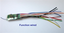
RCT-Rx65c Function wired
Primarily intended for use with the RCT-Tx20 and the Deltang Tx20 transmitter.
Wiring attached to the following pads:
Pad 3 (Blue) - On/off (Channel 2) Momentary action, 0v when channel is Low - can be used to trigger soundcard effects using the F1 button on the Tx20 Pad 4 (Orange) - On/off (Channel 4) Momentary action, 0v when channel is Low - can be used to trigger soundcard effects using the F2 button on the Tx20 Pad 5 (Pink) - On/Off (Channel 3), Latching action, toggle when channel is Low - can be used to triggersoundcard effects, such as diesel engine start/stop using the direction switch (Direction 2) Pad 6 (Grey) - On/Off (Channel 3), Momentary action, 0v when channel is High - can be used to trigger soundcard effects using the direction switch (Direction 1) Pad 7 (Violet) - On/Off (Channel 3), Momentary action, 0v when channel is Low - can be used to trigger soundcard effects using the direction switch (Direction 2) F1 output 'A' (Green) - Front Light (auto), 0v when on disconnected when off - used to operate front light with LED (also mirrors the receiver LED when binding or when the receiver is searching for the transmitter). Negative lead (cathode) from LED connected to the pad and positive lead (anode) of the LED connected to the positive supply from the battery F2 output 'B' (Yellow) - Rear Light (auto), 0v when on disconnected when off - used to operate rear light with LED. Negative lead (cathode) from LED connected to the pad and positive lead (anode) of the LED connected to the positive supply from the battery F3 output 'C' (Brown) - On/Off (Channel 5) Momentary action, 0v (on) when channel is Low - often used for sounding the horn or the whistle on a soundcard when the bind button is pressed
For more information on using these pads see the Support section
Overview of the RCT-Rx65c's features
2.4gHz receiver compatible with DSM2/DSMX
The RCT-Rx65c uses 2.4gHz radio technology and is compatible with DSM2 systems. This means the radio signal is very stable and reliable, being less prone to interference than earlier systems. When a receiver is 'bound' to a transmitter, they create a unique coded signal to communicate with each other, meaning that several transmitters and receivers can safely operate together without the risk of conflicts.
Includes an integrated 3A reversible controller (ESC) for brushed motors
The RCT-Rx65c includes an electronic motor controller (ESC) which controls one loco motor without the need for additional components. This makes it very versatile and economical. It can handle loads of up to 3 amps.
Can be powered by 3-13v (1-3S lipo, 1-4 life, 3-8 nicads, 1 PP3)
Any type of battery can be used to power the RCT-Rx65 or it can be powered from the track. By default, the receiver is programmed to detect the number of lithium-ion batteries connected to it and will automatically cut-out if their voltage drops below safe levels (Low Voltage Cut-off (LVC)). This feature can be easily disabled the the user (or by me on request), if the receiver is going to be run with other types of battery (see paperclip settings)
Cruise Control / Failsafe
The RCT-Rx65c is set to Cruise Control by default. This means that if a loco loses the signal from the transmitter (eg when running through a tunnel), then the loco will continue running at the same speed and in the same direction until it regains the signal. This feature also allows the user to switch off the receiver (eg when a loco is running around a circuit or is in auto-shuttle mode) to save the transmitter's battery power. However this is not essential as I have found that, in general, the PP3 battery which is used to power the receiver lasts for around a year (though this will vary depending on how often the transmitter is used). This feature can be reset by using paperclip settings
Centre-off / Low-off
By default, the RCT-Rx65c operates in centre-off mode - when the speed knob (or joystick) on the transmitter is centred, the loco is stationary. When the speed knob (or stick) is moved from the centre position to the right and the loco moves forward, twist the speed knob (or push the stick) from the central position to the left and the loco moves in reverse. It is possible to reprogram the receiver using paperclip settings to that it interprets the signal from the speed knob on the transmitter to control speed only. When the knob is turned fully to the left, the loco is stationary. As the knob is turned to the right the loco's speed is adjusted accordingly. To change direction, the direction switch is used (Channel 3). The direction can only be changed while the loco is stationary. This feature can be reset using a paperclip setting.
Output pads
A great virtue of the RCT-Rx65c, is the number of output pads which it offers (11 in total) which can be used for a range of purposes. These pads are programmed by default to provide useful outputs but they can also be reprogrammed for other purposes.
Default settings for the pads on the RCT-Rx65c
- Pad 1 - Front Light - Auto action, gives 3.5v when on, 0v when off - Can be connected to an LED with a suitable resistor
- Pad 2 - Rear Light - Auto action, gives 3.5v when on, 0v when off - Can be connected to an LED with a suitable resistor
- Pad 3 - On/Off (Channel 2), Momentary action, 0v when channel is Low
- Pad 4 - On/Off (Channel 4), Momentary action, 0v when channel is Low
- Pad 5 - On/Off (Channel 3), Latching action, toggles from high to low when toggle switch is pressed to the ?? - can be used to trigger soundcard effects such as the starting/stopping of a diesel engine
- Pad 6 - On/Off (Channel 3), Momentary action, 0v when channel is High - can be used to trigger soundcard effects using direction switch (Direction 1)
- Pad 7 - On/Off (Channel 3), Momentary action, 0v when channel is Low - can be used to trigger soundcard effects using direction switch (Direction 2)
- F1 output 'A' - Front Light (auto), 0v when on disconnected when off - used to operate front light with LED (also mirrors the receiver LED when binding or when the receiver is searching for the transmitter)
- F2 output 'B' - Rear Light (auto), 0v when on disconnected when off - used to operate rear light with LED
- F3 output 'C' - On/Off Momentary action (Channel 5), 0v (on) when channel is Low - often used for sounding the horn or the whistle on a soundcard when the bind button is pressed
You may notice there appears to be some repetition in the actions of the pads. In fact, the variations provide the user with very useful pre-programmed outputs to meet a variety of needs from operating lighting to triggering the effects on soundcards. There is more information about the use of output pads on my blog postings - eg Using output pads on RCT/Deltang receivers.
It is also possible for functions of each pad to be re-programmed by the user (or by me on request). For example, output pads can be reprogrammed to provide lighting effects (such as flashing or pulsing lights on, say, a modern diesel shunting loco). In addition the pads can be used as input sensors to trigger events such as sounding the whistle or horn on a soundcard or triggering auto-stop when the loco runs over a magnet positioned between the sleepers. For more information on programming RCT receivers see my blog posting - How to program RCT / Deltang receivers